Toro Australia

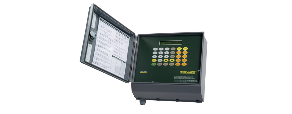
Toro Micro-Master® 4000 Series Controllers
Toro Micro-Master® 4000 Series Controllers


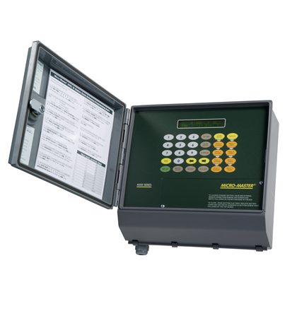
The MicroMaster 4000 controller is ideal for Municipal, Landscape, Turf and Horticultural applications.

16 or 32 station models

16 or 32 station models

Sequential operation

Sequential operation

4 independent programs (A, B, C, D)

4 independent programs (A, B, C, D)

Program On/Off Overlap allows only one or all programs to operate at once

Program On/Off Overlap allows only one or all programs to operate at once

240 VAC or 12VDC in the one unit

240 VAC or 12VDC in the one unit

12 VCD solar power option using standards 24 VAC solenoids

12 VCD solar power option using standards 24 VAC solenoids

14 day calendar

14 day calendar

Station watering options 0-99 hours 99 mins, 1 min increments 0-99 min 99 secs, 1 sec increments

Station watering options 0-99 hours 99 mins, 1 min increments 0-99 min 99 secs, 1 sec increments

30 starts per day each program i.e. A, B, C, D

30 starts per day each program i.e. A, B, C, D

Cyclic irrigation, 0-99 repeat cycles per program start

Cyclic irrigation, 0-99 repeat cycles per program start

Cycle repeats can be varied for each day

Cycle repeats can be varied for each day

User defined program delay between each cycle repeat for Cycle and Soak operation

User defined program delay between each cycle repeat for Cycle and Soak operation

Water Budget feature adjusts 0-250% per each program, 1% increments

Water Budget feature adjusts 0-250% per each program, 1% increments

Reports totaliser for monitoring each irrigation station operational time totals

Reports totaliser for monitoring each irrigation station operational time totals

Sensor Inputs: Prog. A Start; Prog B Start; Reset; Irrigation Hold; Auto Skip; Door Open/Close Status

Sensor Inputs: Prog. A Start; Prog B Start; Reset; Irrigation Hold; Auto Skip; Door Open/Close Status

Remote connection via Windows software for PC applications for easy central location programming and fault reporting

Remote connection via Windows software for PC applications for easy central location programming and fault reporting

Reports Flow as well as Irrigation or Electrical Failures with station skip

Reports Flow as well as Irrigation or Electrical Failures with station skip

Selectable dual pump start facility

Selectable dual pump start facility

Manual Operations 1. Program Start; 2. Station Start; and 3.Time Set Station Start

Manual Operations 1. Program Start; 2. Station Start; and 3.Time Set Station Start

Manual Stop

Manual Stop

Suspend and Restart Feature during irrigation cycle

Suspend and Restart Feature during irrigation cycle

Station to Station Advance during irrigation cycle.

Station to Station Advance during irrigation cycle.

Up to 8 valves per station (depending on solenoid draw, 2amp limit)

Up to 8 valves per station (depending on solenoid draw, 2amp limit)

Permanent Program Memory

Permanent Program Memory

Inter Station Delay 0-250secs

Inter Station Delay 0-250secs

Auto Skip Facility AS1: 0-250 secs at irrigation start to allow system to stabilise AS2: Operational Scanning time/frequency

Auto Skip Facility AS1: 0-250 secs at irrigation start to allow system to stabilise AS2: Operational Scanning time/frequency

Fault Reporting Monitors system flow or pump pressure utilising the 2 Auto skip times.

Fault Reporting Monitors system flow or pump pressure utilising the 2 Auto skip times.

Extensive protection against field and mains power surges

Extensive protection against field and mains power surges

Relay outputs to field valves ensures reliable operation under the most severe conditions.

Isolated logic board protected by additional transformer which diverts surges to earth.

Isolated logic board protected by additional transformer which diverts surges to earth.

Normal Time 1. Time and day 2. Next program and start time. 3. Rain Switch displayed, or power fail signal.

Normal Time 1. Time and day 2. Next program and start time. 3. Rain Switch displayed, or power fail signal.

During irrigation cycle: 1. Program in cycle. 2. Operating station with run time remaining.

During irrigation cycle: 1. Program in cycle. 2. Operating station with run time remaining.

Input power 240 volt 50 Hz Single phase or 12 volt DC
Operating limits 210 VAC to 265 VAC or 11 VDC to 16 VDC
Quiescent 12V input power 15 mA at 12VDC (55 mA with one output relay and pump start relay active), total current = solenoid current + 70mA
Output power Total station capacity, 24 VAC at 2.0 A max. or 12 VDC at 2.0 A max
Superior lightning and surge protection Transformer primary, 275V, 2,500 amp/20 micro sec. Surge protection, A-E, N, E. Transformer secondary, 24 VAC, 6,500 amp/20 micro sec. Field wiring (32 stations and pump start), 6,500 amp/20 micro sec. Large valve wiring terminals, detachable, do not need to remove valve wires for servicing Permanent program memory maintains all saved programs if power fails. No standby battery is required 9 volt Alkaline battery keeps correct time during power failure. (150 hours nominal) Relay outputs to field valves ensure reliable operation in the most rugged conditions Operating Conditions
Dimensions
  • Height: 270 mm
  • Width: 295 mm
  • Depth: 140 mm
Temperature -10°C to 65°C
Download Type Information
Detailed Specifications Specifications